Traction Inverters for Electric Vehicles
Traction inverters are a crucial component of electric vehicles (EVs), responsible for converting direct current (DC) power from the battery into alternating current (AC) power to drive the electric motors. They play a vital role in controlling the speed and torque of the EV’s motors, making them essential for efficient and smooth operation.
Main vs. auxiliary inverters
In most EVs, there are two types of inverters: the main inverter and the auxiliary inverter.
- Main inverter: The main inverter is the primary inverter in the EV, responsible for driving the main traction motor. It handles the majority of the power required to propel the vehicle.
- Auxiliary inverter: The auxiliary inverter is a smaller inverter that is used to power the vehicle’s auxiliary systems, such as the air conditioning, power steering, and infotainment systems.
The main inverter is typically a much larger and more powerful inverter than the auxiliary inverter. It is designed to handle the high currents and voltages required to drive the main traction motor. The auxiliary inverter, on the other hand, is designed to handle lower currents and voltages, as it is only responsible for powering the vehicle’s auxiliary systems.
Key components of a traction inverter
A traction inverter is a critical component in electric vehicles (EVs), responsible for converting the direct current (DC) from the vehicle’s battery pack into the alternating current (AC) required by the electric motor. Understanding its key components is essential for grasping how EVs operate efficiently.
Power semiconductor devices
At the heart of the traction inverter are the power semiconductor devices, which include insulated-gate bipolar transistors (IGBTs) or silicon carbide (SiC) metal-oxide-semiconductor field-effect transistors (MOSFETs). These devices play a vital role in high-frequency switching, enabling the conversion of DC input into the desired AC waveform. Their performance directly influences the efficiency and responsiveness of the entire inverter system.
Gate drive circuitry
Complementing the power semiconductor devices is the gate drive circuitry. This component is responsible for providing the appropriate control signals that ensure the semiconductor devices switch on and off at the right times. Proper timing is crucial, as it determines the inverter’s ability to generate a smooth and effective AC output for the motor.
DC-link capacitor
The DC-link capacitor serves as a filter for the DC input from the battery pack. By smoothing out any ripple or fluctuations in voltage, it helps maintain a stable and consistent input to the power semiconductor devices. This stability is essential for reliable inverter operation and contributes to the overall performance of the vehicle.
Cooling system
Given that the traction inverter generates a significant amount of heat during operation, an effective cooling system is essential. This typically includes a heatsink, fan, and/or liquid cooling system designed to dissipate heat and keep the inverter’s operating temperature within an acceptable range. Efficient cooling ensures the longevity and reliability of the inverter.
Control and monitoring circuitry
The control and monitoring circuitry manages the overall operation of the traction inverter. This includes controlling the switching of the power semiconductor devices, monitoring temperature and current levels, and providing feedback to the vehicle’s main control system. This component is crucial for maintaining optimal performance and safety.
EMI/EMC filtering
The high-frequency switching in traction inverters can generate electromagnetic interference (EMI), potentially disrupting other vehicle systems. Effective EMI/EMC (electromagnetic compatibility) filtering is necessary to ensure that the inverter operates without causing interference, contributing to the smooth functioning of the entire vehicle.
Packaging and integration
Finally, the design and packaging of the traction inverter play a crucial role in optimizing its performance, efficiency, and reliability. Proper integration with the vehicle’s powertrain and electrical systems ensures that the inverter operates seamlessly within the overall architecture of the EV.
Figure 1 shows the block diagram of a typical main traction inverter for electric vehicles.

Traction inverter topologies
Traction inverters play a crucial role in electric vehicles (EVs) by converting direct current (DC) from the battery into alternating current (AC) to drive the electric motor. There are several different topologies for traction inverters, each with its advantages and disadvantages. The most common topologies are listed hereafter.
Two-level topology
The two-level topology is the most prevalent design for traction inverters. It is characterized by its simplicity and cost-effectiveness, making it a popular choice for many applications. This topology typically consists of a basic inverter circuit that switches between two voltage levels, which allows for straightforward control of the motor. However, while it is easy to implement, it may not provide the highest efficiency or the lowest harmonic distortion compared to more complex designs.
Three-level topology
The three-level topology enhances the performance of traction inverters by introducing an additional voltage level. This design can significantly improve the efficiency of the inverter and reduce the harmonic distortion of the AC waveform produced. By utilizing three voltage levels, the inverter can create a smoother output waveform, which is beneficial for the operation of electric motors. This topology also allows for better thermal management and can reduce the stress on the switching devices, leading to improved reliability.
Multilevel topology
Multilevel inverters (MLIs) represent an advanced approach to traction inverter design. These systems can further enhance efficiency and minimize harmonic distortion by using multiple voltage levels—often more than three. The increased number of levels allows for a more refined output waveform, which can lead to better performance in terms of torque and speed control of the electric motor. Additionally, multilevel topologies can distribute power losses more evenly across the switching devices, which can improve the overall thermal performance and lifespan of the inverter.
The choice of traction inverter topology is critical in optimizing the performance of electric vehicles. Each topology offers unique benefits and trade-offs, making it essential for engineers to select the appropriate design based on the specific requirements of the application.
Future trends in traction inverters
Traction inverters are constantly being improved to make them more efficient, powerful, and reliable. Some of the future trends in traction inverters include:
- Wider Bandgap Semiconductors: These materials, such as silicon carbide (SiC) and gallium nitride (GaN), can operate at higher temperatures and frequencies than traditional silicon-based semiconductors. This can lead to more efficient and powerful traction inverters.
- Modular Design: Modular traction inverters can be easily scaled to meet the needs of different EVs. This can make them more flexible and cost-effective.
- Integration with Other Components: Traction inverters can be integrated with other components, such as batteries and electric motors, to improve the overall efficiency and performance of the EV.
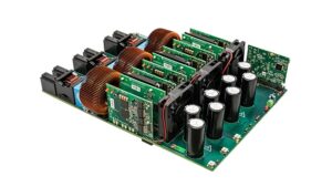
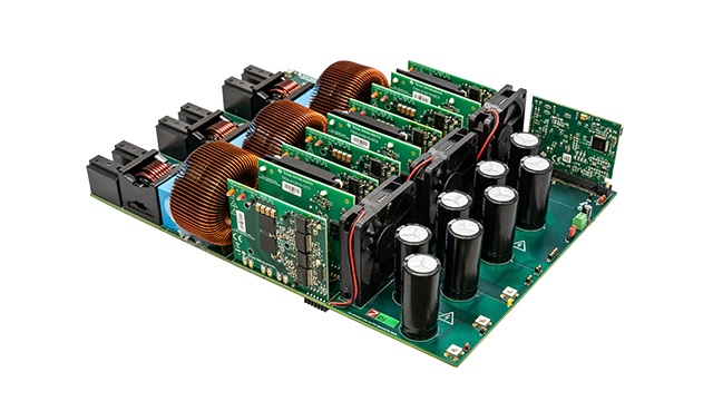
Texas Instruments TIDA-010210 is a GaN-based reference design featuring an 11-kW, bidirectional, three-phase, and three-level Active Neutral-Point Clamped (ANPC) topology.
This reference design (Figure 2) offers a framework for the implementation of a three-level, three-phase, gallium nitride (GaN) based ANPC inverter power stage. The use of fast-switching power devices makes it possible to switch at a higher frequency of 100 kHz, reducing the size of magnetics for the filter and increasing the power density of the power stage. The multilayer topology enables the utilization of 600-V rated power components at elevated DC-bus voltages of up to 1000 V. The diminished switching voltage stress decreases switching losses, yielding a peak efficiency of 98.5%.

Conclusion
Traction inverters are a critical component of EVs, responsible for converting DC power from the battery into AC power to drive the electric motors. They are constantly being improved to make them more efficient, powerful, and reliable. As EVs become more popular, traction inverters will play an increasingly important role in the automotive industry.

